50V 105M 1UF 5.08mm ±20% Radial Lead MLCC
APPROVAL SPECIFICATION FOR LEADED TYPE MLCC
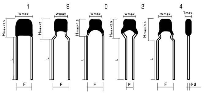
Lead Type Code

| Part number | N/A |
| Description | 50V/105/K/F5.08/L24/X7R(Ⅱ)/0805 |
| Customer P/N | |
| Dielectric class | Class 2 |
| Rated voltage | 50Vdc |
| Capacitance | 1uF ±10% @ 1kHz 1.0V 25ºC |
| Tangent of loss angle | 0.035 max @ 1kHz 1.0V 25ºC |
| Testing voltage | 100Vdc (Charge/discharge 2mA max) 3s PASS |
| Insulation resistance | 1000MΩ min @ 100V 60s, RH≤70% |
| Temperature characteristics | X7R(Ⅱ) ΔC/C: ±15% @ -55ºC~125ºC |
| W (Weight) | 5mm max |
| H (Height) | 4.2mm max |
| T (Thickness) | 3.2mm max |
| F (Lead spacing) | 5.08mm±0.8mm |
| L (Lead length) | 24mm±4.0mm |
| ød (Lead diameter) | 0.45mm±0.05mm |
| Marking | 105 |
| No. | Item | Specifications | Testing Method |
| 1 | Operating temp. range | -55ºC~125ºC | |
| 2 |
Rated voltage
(U R )
|
100V |
The rated voltage is defined as the maximum voltage which may be applied
continuously to the capacitor within the operating temperature range.
When AC voltage is superimposed on DC voltage, Vp-p or Vo-p, whichever is
larger, should be maintained within the rated voltage range.
|
| 3 |
Appearance (APP)
and Dimension
|
No marked defect on appearance form and
dimensions are within specified range.
|
The capacitor should be visually inspected for evidence of defect. Dimensions should be measured with slide calipers. |
| 4 | Marking | To be easily legible. | The capacitor should be visually inspected. |
| 5 | Capacitance (C R ) | 100000pF±10% |
The capacitance, tanδ should be measured at 25°C±1°C with the following
conditions. 1kHz 1.0Vrms
|
| 6 | Tangent of loss angle (tanδ) | 0.035 max | Same as above |
| 7 |
Insulation Resistance
(IR)
|
1000MΩ min |
The insulation resistance should be measured with a DC voltage not exceeding
the following voltage at normal temperature and humidity and less than 1 minute
of charging. 100VDC
|
| 8 |
Testing Voltage
(TV)
|
No failure. |
The capacitor should not be damaged when test voltages of below are applied
between the lead wires for 1 to 5 sec.(Charge/Discharge current ≤ 2mA) 250VDC
|
| 9 | Terminal Tensile Strength |
Lead wire should not be cut off capacitor
should not be broken.
|
Fix the body of the capacitor and apply a tensile weight gradually to each lead
wire in the radial direction of the capacitor up to 10N and keep it for 10±1 sec.
|
| 10 | Terminal Bending Strengt |
Lead wire should not be cut off capacitor
should not be broken.
|
Each lead wire should be subjected to 5N of weight and bent 90° at the point of
egress, in one direction, then returned to its original position and bent 90° in the
opposite direction at the rate of one bent in 2 to 3 sec.
|
| 11 | Solderability of Leads |
Lead wire should be soldered with uniform
coating on the axial direction over 3/4 of the
circumferential direction.
|
The lead wire of a capacitor should be dipped into molten solder for 3±0.5 sec.
The depth of immersion is up to about 1.5 to 2.0mm from the root of lead wires.
Temp. of solder: Lead Free Solder (Sn-3Ag-0.5Cu) 245±5°C H63 Eutectic Solder 235±5°C |
| 12 | Soldering Effect |
APP:No marked defect ΔC/C:±10% IR:More than 30% initial specified value. |
The lead wires should be immersed in solder of 260±5°C up to 1.5 to 2.0mm
from the root of terminal for 3.5±0.5 sec.
Post-treatment: Capacitor should be stored for 12 h at room condition. |
| 13 |
Vibration
Resistance
|
APP:No marked defect Cr:Per Item 5. tanδ:Per Item 6. |
The capacitor should be firmly soldered to the supporting lead wire and vibrated
at a frequency range of 10 to 55Hz, 1.5mm in total amplitude, with about a 1
minute rate of vibration change from 10Hz to 55Hz and back to 10Hz.
Apply for a total of 6 hours, 2 hours each in 3 mutually perpendicular directions. |
| 14 | Temperature characteristics | ΔC/C: ±15% |
The capacitance measurement should be made at each step specified in below.
Stwp Temperature (±1ºC)
1 +20
2 -55 (Y5V: -30)
3 +20
4 +125 (Y5V, X5R: +85)
5 +20
|
| 15 |
Humidity
Loading
|
APP:No marked defect ΔC/C:±10% tanδ:Less than 200% initial specified value. IR:More than 25% initial specified value. |
Apply the rated voltage for 500±12 hours at 40±2°C in 90 to 95% relative
humidity.
Post-treatment: Capacitor should be stored for 24 h at room condition. |
| 16 |
High
Temperature
Load
|
APP:No marked defect ΔC/C:±10% tanδ:Less than 150% of initial specified value. IR:More than 50% initial specified value. |
Apply a DC voltage of 150% of the following voltage for 1000+48/-0 hours at
125±2°C (X5R, Y5V: 85°C) with a relative humidity of 50% max.
(Charge/discharge current ≤2mA) 150VDC Post-treatment: Capacitor shall be stored for 24 h at room condition. |
| 17 |
Temperature and
Immersion Cycle
|
APP:No marked defect ΔC/C:±10% tanδ:Less than 150% of initial specified value. IR:More than 30% initial specified value. |
Temperature cycling shall be measured in the following test. Step Temperature Time 1 -25±2°C 30min 2 +125±2°C(X5R, Y5V: 85°C) 30min Cycle times: 5 cycles Post-treatment: Capacitor shall be stored for 12 h at room condition. |
: HV Ceramic Capacitors
: +86 13689553728
: +86 13689553728
: 深圳市福田区天安数码城天翔大厦9B2